













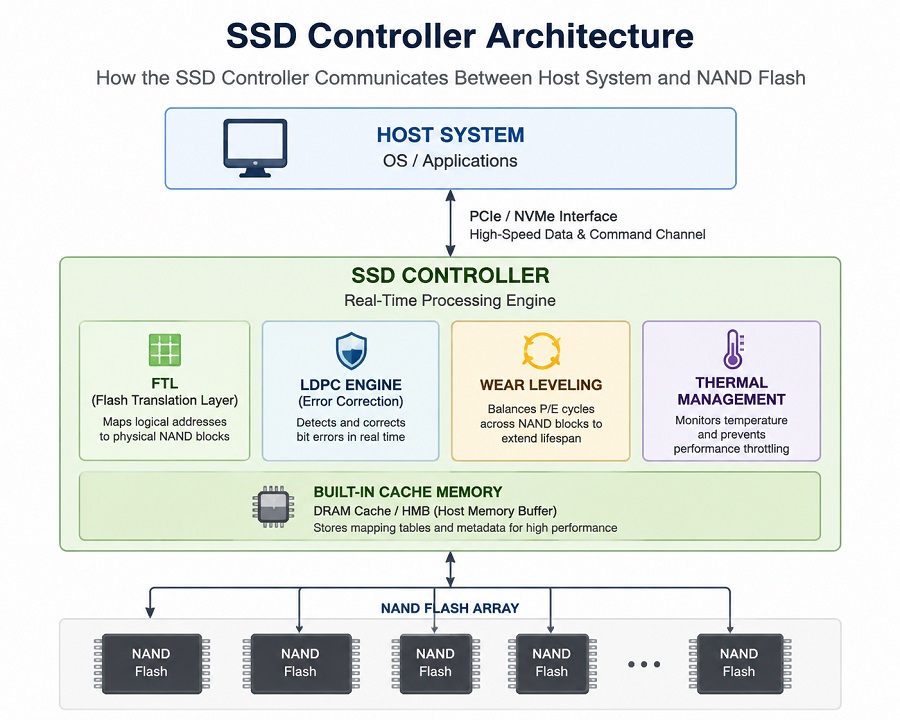
In our storage testing lab, we regularly see two PCIe 4.0 SSDs built with identical 3D TLC flash packages diverge sharply within 15 minutes of continuous writing. One maintains a predictable 3,000 MB/s line, while the other craters to legacy SATA speeds as onboard temperatures climb. The culprit is almost never the NAND itself—it comes down to the real-time processing engine sitting right next to it: the SSD controller.
+---------------------------------------------------+
|                  Host System                      |
+---------------------------------------------------+
                          |
             PCIe / NVMe Bus Interface
                          |
+---------------------------------------------------+
|                   SSD Controller                  |
|  (FTL | LDPC Engine | Wear Leveling | Thermal Mgt)|
+---------------------------------------------------+
                          |
     -------------------------------------------
     |           |           |                 |
 +-------+   +-------+   +-------+         +-------+
 | NAND  |   | NAND  |   | NAND  |   ...   | NAND  |
 +-------+   +-------+   +-------+         +-------+
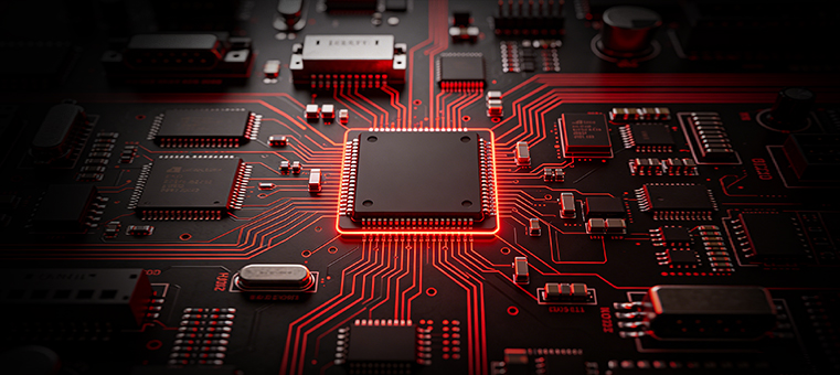
Raw NAND Flash is fundamentally passive silicon. On its own, it has no native mechanism to track logical file locations, balance physical cell wear, or compensate for voltage drift as oxide layers degrade. The controller acts as an embedded multi-core processor that transforms raw flash into a stable, host-compliant storage drive.
FTL (Flash Translation Layer): The Traffic Controller of Data
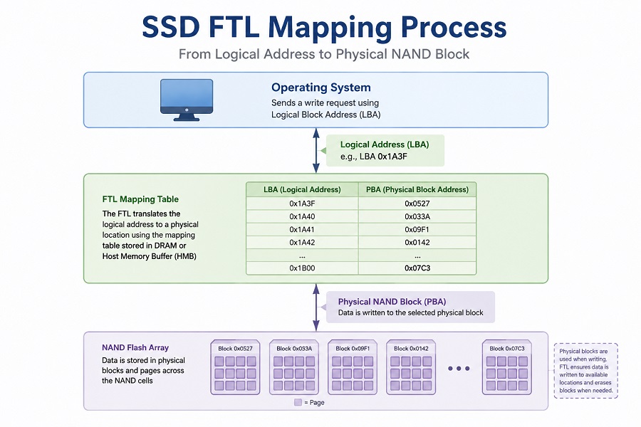
Unlike magnetic hard drives, NAND flash cannot overwrite existing data directly. Storage engineers face a strict physical constraint: data is written at the Page level (4KB–16KB), but must be erased at the Block level (several MBs).
When the host OS sends a write instruction, it operates in Logical Block Addresses (LBA). The controller’s Flash Translation Layer (FTL) intercepts these requests and maps them to available Physical Block Addresses (PBA) across the flash array.
Logical Address (LBA) → [ SSD Controller (FTL) ] → Physical NAND Block (PBA)Fetching mapping tables with zero latency requires fast memory lookup. High-performance drives integrate dedicated onboard DRAM cache, whereas cost-optimized architectures utilize Host Memory Buffer (HMB) over the PCIe bus. How a controller manages this lookup architecture directly determines random 4K throughput, as detailed in our guide on DRAM vs DRAM-less SSD Explained.
Core Controller Engineering in Action
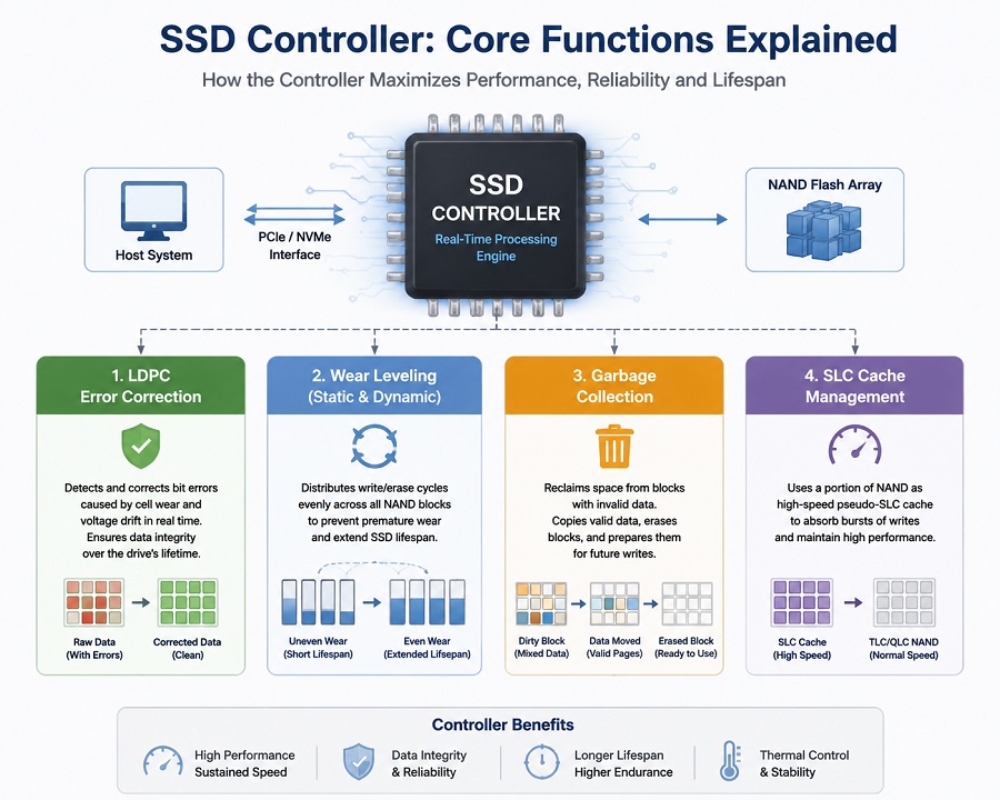
Modern SSD controllers execute background pipelines continuously to mitigate raw NAND degradation while pushing bus utilization to its limits.
Handling Tight Voltage Margins (LDPC Engine)
Increasing storage density shrinks the electrical voltage windows required to determine cell states:
- TLC NAND manages 8 distinct voltage levels per cell.
- QLC NAND squeezes 16 voltage levels into the same physical footprint.
Narrow read voltage margins leave high-density cells susceptible to charge leakage. For a breakdown of cell density trade-offs, refer to our analysis on TLC vs QLC SSD: Performance and Endurance.
To preserve data integrity, the controller deploys a hardware-level Low-Density Parity-Check (LDPC) engine. As Raw Bit Error Rates (RBER) increase over drive usage, LDPC recalculates corrupted data on the fly before bit errors hit the OS layer.
Preventing Premature Cell Death (Wear Leveling)
NAND memory cells survive only a finite number of Program/Erase (P/E) cycles before physical insulation breaks down. Unmanaged write operations to static addresses would destroy individual blocks within months.
Controllers implement **Static and Dynamic Wear Leveling** algorithms. By tracking write counts across all physical blocks, the controller routinely shifts static, cold data (rarely modified files) into worn blocks, freeing up high-health blocks for incoming high-frequency write streams. This directly governs total drive lifespan, as covered in SSD TBW Explained: What It Means for Lifespan.
Incoming Writes → [ Controller ] → Distributes evenly across high-health blocks
                                 → Parks static files in older, worn blocks
Housekeeping Under the Hood (Garbage Collection & SLC Buffer)
Deleting a file marks logical space as invalid, but physical block erasure takes significant time. During system idle times, the controller executes **Garbage Collection**:
- Consolidates valid pages from dirty blocks into a fresh target block.
- Executes a full block erase on the dirty block.
- Returns the clean block to the available write pool.
To absorb rapid sustained writes, controllers allocate a dynamic section of native flash to operate in single-bit pseudo-SLC mode. Once this cache exhausts during heavy file transfers, speeds drop to native NAND write levels. If your drive experiences sustained write drops, see our diagnostic breakdown on Why Is My SSD Slow After Installation?.
Silicon Is Only Half the Equation: The Role of Firmware
Two drives built with identical controller silicon and flash packages often exhibit completely different throttle curves and latency profiles. That divergence is driven by **Firmware**—the embedded logic running on the controller cores.
Firmware engineering is a balance of operational compromises:
- Overly aggressive pseudo-SLC cache clearing boosts synthetic benchmark scores but increases Write Amplification Factor (WAF), shortening cell life.
- Conservative thermal throttling prevents heat damage but can lead to sharp, noticeable speed drops during sustained transfers.
- Background FTL compaction must be balanced against real-time host I/O queue depths to avoid severe latency spikes.
Proper firmware tuning determines whether an SSD is optimized for low-power consumer devices or sustained, low-latency enterprise workloads.
SSD Controller vs NAND Flash: Understanding Their Roles in SSD Performance
Evaluating an SSD purely by its flash type or its controller model overlooks how the two function as an integrated system.
- NAND Flash provides the physical storage array, setting capacity limits, maximum cell endurance, and base voltage tolerances.
- The SSD Controller functions as the operational engine, directing write paths, executing LDPC routines, managing thermal boundaries, and mitigating cell wear.
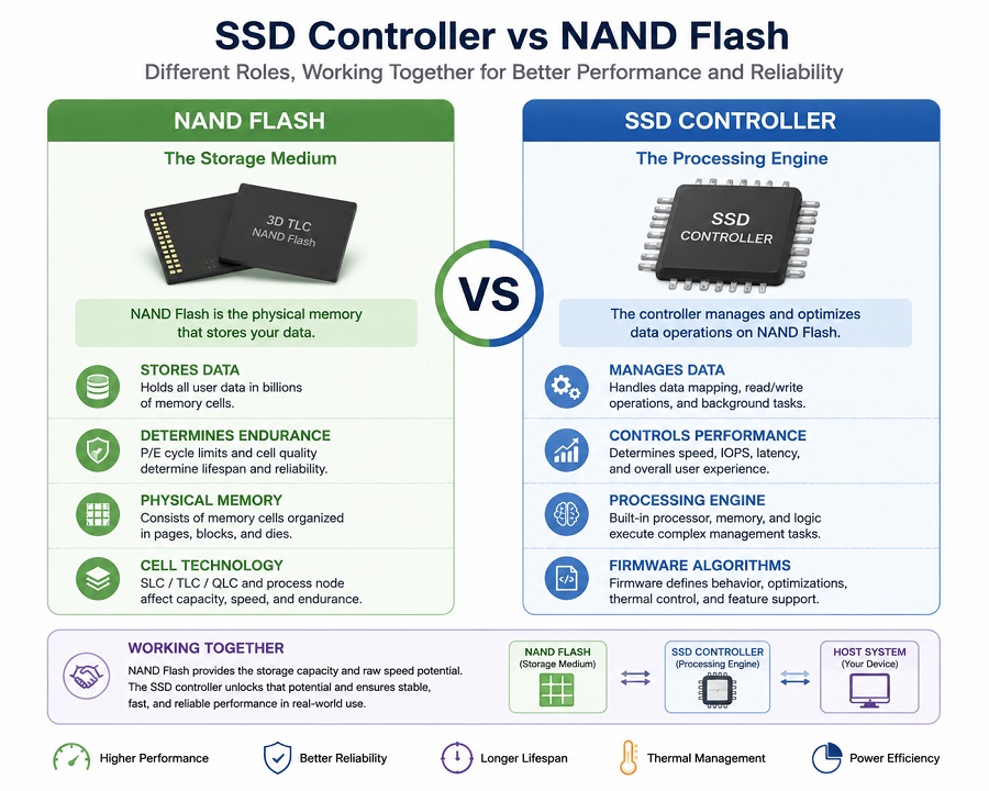
| Component | Main Function | Impact on SSD |
|---|---|---|
| NAND Flash | Stores electrical data | Capacity, endurance, data retention |
| SSD Controller | Manages NAND operations | Performance, stability, efficiency |
| Firmware | Controls optimization algorithms | Consistency and workload behavior |
Advanced NAND flash paired with inefficient controller algorithms will exhibit latency instability under heavy queues. Conversely, even a high-tier controller cannot overcome low-grade flash with high initial bit error rates. Long-term reliability requires matched controller engineering, tuned firmware, and verified flash quality.
However, SSD reliability is not only determined during design and manufacturing. After installation, users also need practical ways to monitor how the drive is aging over time.
Health indicators such as SMART data, temperature, total host writes, and endurance usage can provide useful information about SSD condition.
For a practical guide on checking SSD lifespan and drive health, see:
SSD Health Check: How to Check SSD Lifespan and Condition (2026 Guide)
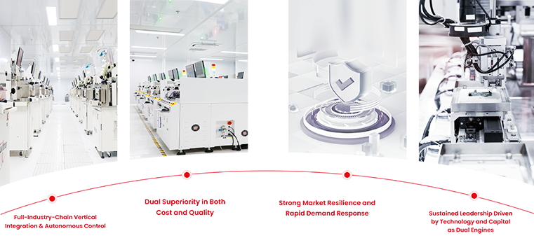
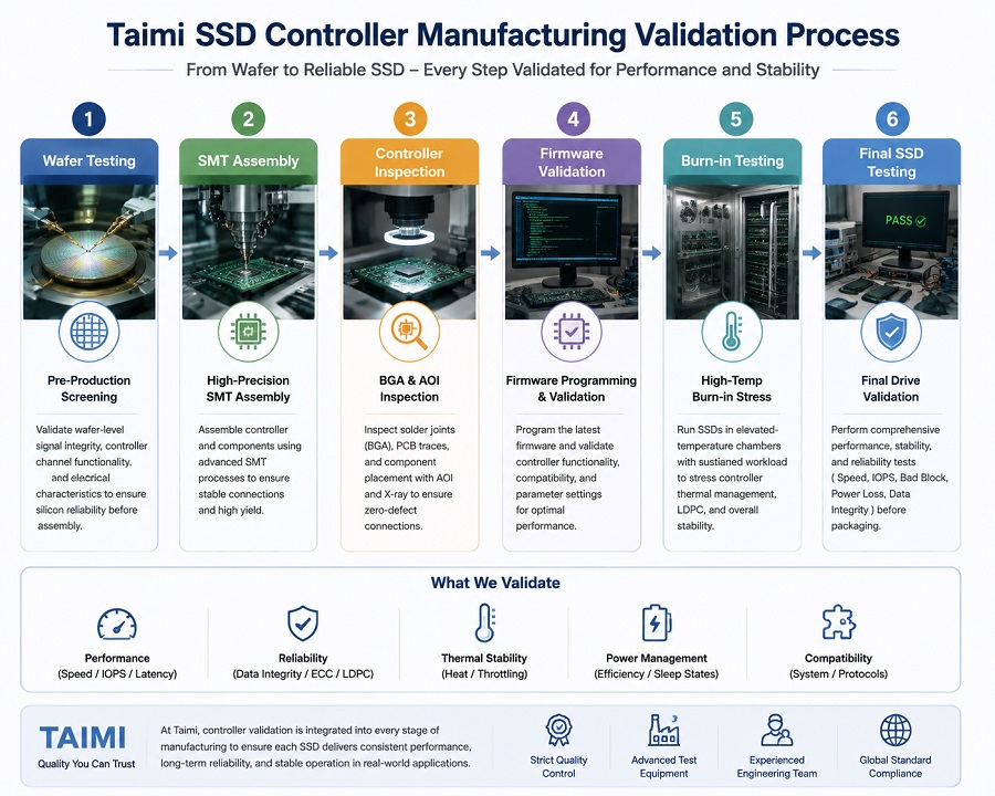
How Controllers Are Validated on the Factory Floor
Ensuring controller hardware executes reliably across varying flash lots requires systematic validation during drive assembly.
Pre-Production Screening → SMT BGA Inspection → High-Temp Burn-In Stress → Final Drive ValidationAt Taimi, controller validation is integrated directly into manufacturing workflows:
- Pre-Production Screening: Validating wafer-level signal integrity and controller channel responses before high-speed surface-mount assembly.
- SMT BGA Inspection: Inspecting solder joint consistency between controller contacts and PCB trace lines to maintain signal integrity over thermal cycles.
- Burn-in Stress Testing: Driving assembled boards through elevated-temperature environmental chambers to stress controller thermal throttle logic and verify LDPC recovery engines under load.
Quick Technical Summary
| Component | Physical Role | Controller Operational Duty |
|---|---|---|
| NAND Flash | Stores physical electrical charge | Coordinates read/write timing & voltage sensing |
| FTL & Caching | Maps OS logic to physical blocks | Manages DRAM / HMB lookup tables for fast 4K IOPS |
| ECC / LDPC Engine | Fixes bit drift as cells age | Corrects raw bit errors in real-time to avoid data corruption |
| Wear Leveling | Manages cell degradation | Balances P/E cycles to prevent premature drive failure |
| Firmware | Controls SSD behavior | Optimizes performance, power management, and reliability |
Frequently Asked Questions About SSD Controllers
What does an SSD controller do?
An SSD controller manages communication between the host system and NAND Flash memory. It controls data mapping, error correction, wear leveling, performance optimization, and reliability functions.
Does an SSD controller affect SSD speed?
Yes. The controller affects data processing efficiency, random performance, sustained write speed, and how effectively NAND Flash is managed.
Does an SSD controller affect lifespan?
Yes. Functions such as ECC, wear leveling, and garbage collection directly influence NAND endurance and SSD lifespan.
Why do SSDs slow down during large file transfers?
When the SLC cache is full, the controller must write data directly to native TLC or QLC NAND while managing background operations. Controller efficiency determines how smoothly performance is maintained.
Can SSD firmware improve controller performance?
Yes. Firmware updates can improve SSD compatibility and stability by refining controller algorithms, adjusting thermal management behavior, and addressing issues discovered during product validation.
What is the difference between SSD controller and NAND Flash?
NAND Flash stores user data, while the SSD controller manages how data is written, accessed, corrected, and optimized. Both components are essential for SSD performance and reliability.
Focusing purely on advertised burst speeds ignores how an SSD behaves under sustained operational loads. NAND flash provides raw storage density, but the controller is the operational processor that maintains host throughput, regulates thermal envelopes, and protects data integrity over years of continuous use.
From a storage engineering perspective, controller selection and firmware execution dictate whether a drive maintains steady-state performance past initial benchmark runs. Real-world drive endurance relies on balanced hardware design, validated flash selection, and rigorous quality control across production runs.
Further Reading & Selection Guide Understanding how the SSD controller impacts drive stability and longevity is only half the battle; choosing the right capacity tier ensures you get the performance headroom you need. Explore our complete breakdown to make the right choice: [How Much SSD Storage Do You Need? 512GB vs. 1TB vs. 2TB SSD].